Turntable
(EN)
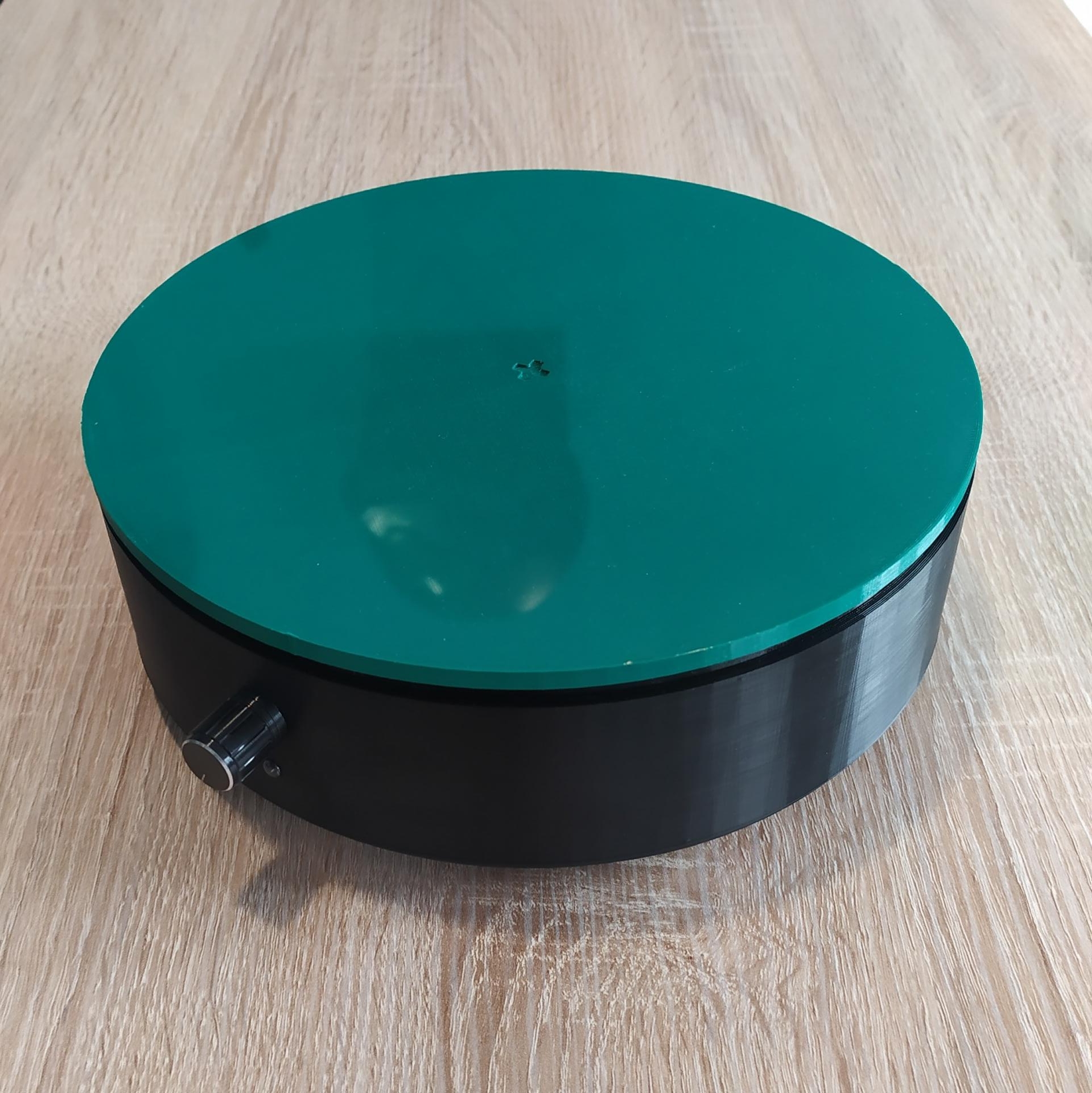
I wanted to be able to make a 360° video of each of my projects in order to be able to integrate it into a website or simply to serve as a presentation video. That's why I made my own turntable. The realization of this project is rather simple but works relatively well!
(FR)
Je voulais avoir la possibilité de faire une vidéo 360° de chacun de mes projets afin de pouvoir l'intégrer dans un site web ou simplement pour servir de vidéo de présentation. C'est pourquoi j'ai fabriqué mon propre plateau tournant. La réalisation de ce projet est plutot simple mais fonctionne relativement bien !
Nomenclature / Nomenclature
(EN)
- 1 Arduino Nano Every (or Arduino Nano)
- 1 10kΩ potentiometer
- 1 5mm LED
- 1 600Ω resistor
- 1 potentiometer cap
- 1 rocker switch (3 pins)
- 1 SM-S40303R servomotor
- 1 power connecteur (5.5x2.1mm)
- 1 LS2596S module (optional)
- 2 M3xmm screws (optional)
- Electric wires
- 3D filament
- 4 small rubber feet
- 4 M3x16mm screws
- 7 M2 nuts
- 7 M2x20mm screws
- 2 M2x8mm screws
- Some hot glue
- Some silicone lubricant
The total price is around 20-25€
(FR)
- 1 Arduino Nano Every (or Arduino Nano)
- 1 potentiomètre 10kΩ
- 1 LED 5mm
- 1 résistance 600Ω
- 1 bouchon de potentiomètre
- 1 interrupteur à bascule (3 broches)
- 1 servomoteur SM-S40303R
- 1 connecteur d'alimentation (5,5x2,1mm)
- 1 module LS2596S (optionnel)
- 2 vis M3xmm (optionnelles)
- Fils électriques
- Filament 3D
- 4 petits pieds en caoutchouc
- 4 vis M3x16mm
- 7 écrous M2
- 7 vis M2x20mm
- 2 vis M2x8mm
- Un peu de colle chaude
- Un peu de lubrifiant silicone
Le prix total est d'environ 20-25€
Electronic diagram / Schéma électronique
(EN)
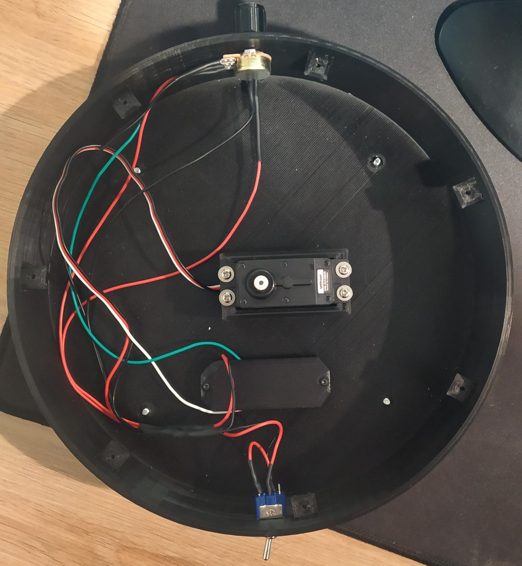
The (+) pin of the power connector is connected to the first pin of the rocker switch so that the system can be turned on/off. The (-) of the connector and the second pin of the (+) switch are used to power the Arduino, the servomotor and the potentiometer. However, if the power supply used is greater than 5V, it is possible to add an LS2596S step-down module in order to lower the voltage of the supply to 5V. In this case, simply power the module and set the output voltage to 5V using the module's small potentiometer. Be careful, this must be done before connecting the Arduino, the servomotor and the potentiometer so as not to burn them out! The remaining potentiometer pin (the middle one) is connected to Arduino pin A7 (analog pin) and the servomotor signal pin is connected to Arduino pin D3 (digital/PWM pin).
(FR)
La broche (+) du connecteur d'alimentation est connectée à la première broche de l'interrupteur à bascule afin de pouvoir allumer/éteindre le système. Le (-) du connecteur et la seconde broche de l'interrupteur (+) permettre d'alimenter l'Arduino, le servomoteur ainsi que le potentiomètre. Cependant, si l'alimentation utilisée est supérieure à 5V, il est possible d'ajouter un module abaisseur de tension LS2596S afin d'abaisser la tension de l'alimentation à 5V. Dans ce cas, il suffit d'alimenter le module et de régler la tension de sortie à 5V grâce au petit potentiomètre du module. Attention, C'est à faire avant de connecter l'Arduino, le servomoteur et le potentiomètre pour ne pas les faire cramer ! La broche restante du potentiomètre (celle du milieu) est connectée à la broche A7 de l'Arduino (broche analogique) et la broche signal du servomoteur est connectée à la broche D3 de l'Arduino (broche digital/PWM).
3D printing / Impression 3D
(EN)
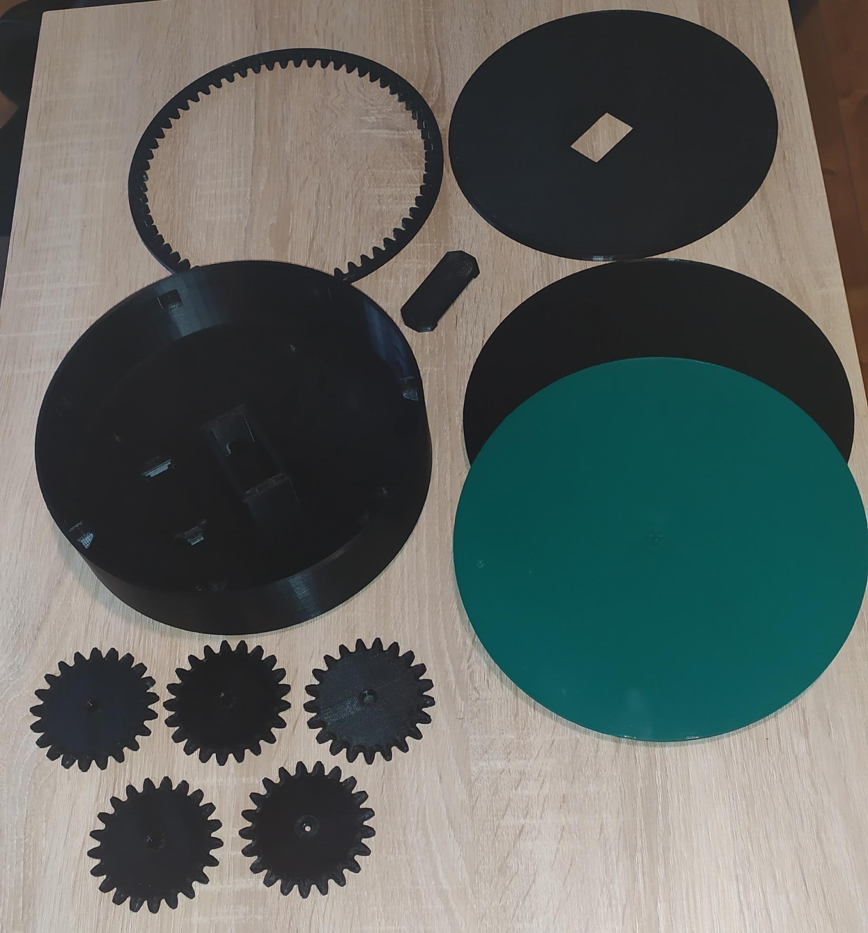
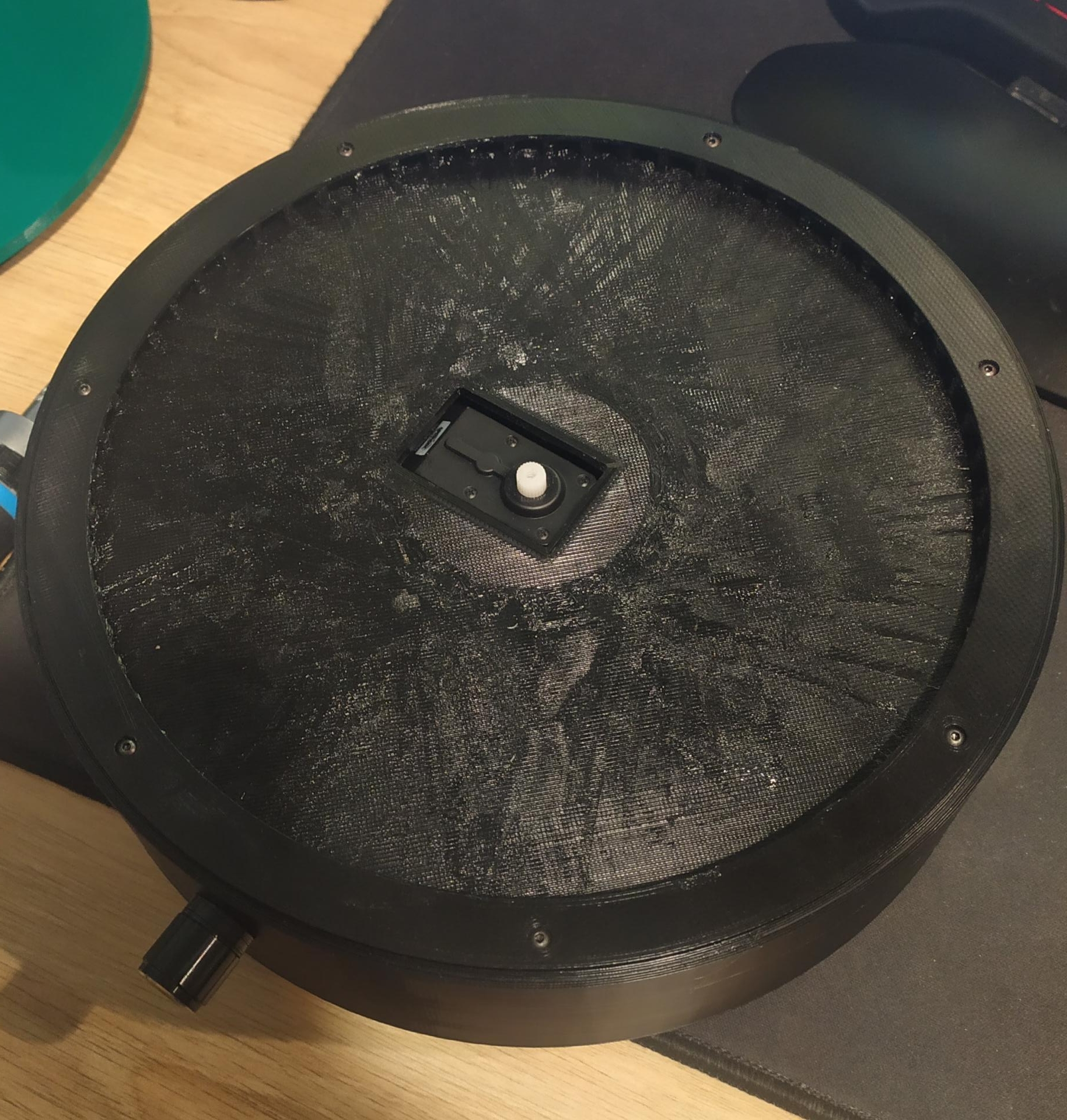
I would first like to clarify that the 3D printing and photos of my project may not correspond 100% to the 3D modeling. I made improvements after assembling my project without re-printing it.
The turntable has a dimension of more than 20cm in diameter. On the front is the LED to indicate whether the platter is on/off as well as the potentiometer to change the direction and speed of rotation. On the back is the rocker switch to turn on/off the turntable as well as the power connector. Finally, there is a specific slot for the servomotor, the Arduino as well as for the LS2596S module if necessary.
Link to Cults3D/Thingiverse
(FR)
Je voudrais d'abord préciser que l'impression 3D et les photos de mon projet peuvent ne pas correspondre à 100% à la modélisation 3D. J'ai fait des améliorations après avoir assemblé mon projet sans pour autant l'avoir ré-imprimé.
Le plateau tournant a une dimension de + de 20cm de diamètre. A l'avant se trouve la LED pour indiquer si le plateau est allumé/éteint ainsi que le potentiomètre afin de changer la direction et la vitesse de rotation. A l'arrière se trouve l'interrupteur à bascule pour allumer/éteindre le plateau ainsi que le connecteur d'alimentation. Enfin, il y a un emplacement spécifique pour le servomoteur, l'arduino ainsi que pour le module LS2596S si il est nécessaire.
Lien vers Cults3D/Thingiverse
Programming / Programmation
(EN)
Here is the code to upload to the Arduino. If you don't have it, you will need to download and install the Arduino IDE. I used the "Servo" library to make the servomotor work. So I initialized the servomotor, and depending on the position of the potentiometer, the servomotor will rotate at a certain speed and in a certain direction.
Link to the Arduino IDE tutorial
(FR)
Voici le code à téléverser dans l'Arduino. Si vous ne l'avez pas, vous allez devoir télécharger et installer l'IDE Arduino. J'ai utilisé la librairie "Servo" afin de faire fonctionner le servomoteur. J'ai donc initialisé le servomoteur, et en fonction de la position du potentiomètre, le servomoteur va tourner à une certaine vitesse et dans un certain sens.
Lien vers le tutoriel Arduino IDE
- File name: Turntable
- Size: 494 b
Assembly / Assemblage
(EN)
An assembly video is being prepared, it is coming as soon as possible!
(FR)
Une vidéo s'assemblage est en cours de préparation, elle arrive au plus vite !
(EN)
- First, I prepare the potentiometer, the LED/resistor assembly, the rocker switch and the power connector by soldering the necessary electrical wires to their pins.
- Then, I screw the feet and the servomotor so that its axis is in the center of the base, and I fit the first elements in their locations.
- I weld the elements to each other as indicated in the electronic diagram. It is possible to add small XH type connectors to make the elements removable.
- After that, I fix the Arduino with its cover thanks to 2 M2x8mm screws, and the LS2596S module (if it has one) thanks to 2 M3xmm screws. Before closing the turntable, we fix the cables with hot glue so that the interior is cleaner.
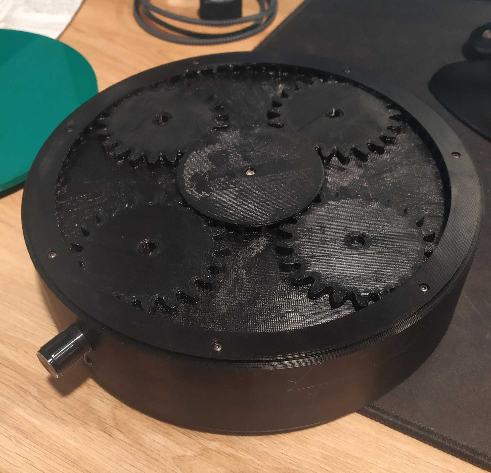
- And finally, we place the nuts in their housing in order to screw the ring and the gear support. Then we place the 4 gears of the plate and the central gear (with its screw) to finally place the plate there.
In order to slightly reduce the noise associated with the friction of the gears, it is possible to file/sand the gears or put a little silicone lubricant.
(FR)
- Dans un premier temps, je prépare le potentiomère, l'ensemble LED/résistance, l'interrupteur ainsi que le connecteur d'alimentation en soudant les fils électriques nécessaires à leurs broches.
- Ensuite, je visse les pieds et le servomoteur afin que son axe soit au centre de la base, et j'emboite les premiers éléments dans leur emplacements.
- Je soude les éléments les uns aux autres tel que c'est indiqué dans le schéma électronique. Il est possible d'ajouter des petits connecteurs de type XH afin de rendre les éléments amovibles.
- Après ça, je fixe l'Arduino avec son couvercle grâce à 2 vis M2x8mm, et le module LS2596S (si il en a un) grâce à 2 vis M3xmm. Avant de refermer le plateau, on fixe les câbles avec de la colle chaude pour que l'intérieur soit plus propre.
- Et enfin, on place les écrous dans leur logement afin d'y visser l'anneau et le support d'engrenages. Puis on place les 4 engrenages du plateau et l'engrenage centrale (avec sa vis) pour enfin y déposer le plateau.
Afin de réduire légèrement les bruits liés aux frottements des engrenages, il est possible de limer/poncer les engrenages ou de mettre un peu de lubrifiant silicone.
Future improvements / Futures améliorations
(EN)
- Possibility of adding a battery and a battery charge/discharge module in order to be able to use the tray without an electrical outlet.
- Possibility to change the Arduino by an ESP32 in order to be able to control the board thanks to a smartphone application.
(FR)
- Possibilité d'ajouter une batterie et un module de charge/décharge de batterie afin de pouvoir utiliser le plateau sans prise électrique.
- Possibilité de changer l'Arduino par un ESP32 afin de pouvoir contrôler le plateau grâce à une application de smartphone.
Last edited: Thu 17 august 2023
Add a comment


