WALL-E Replica

(EN)

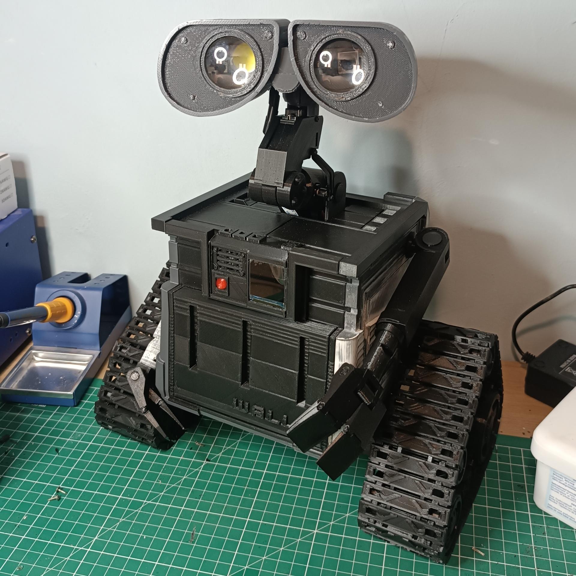
WALL-E is a cute little robot featured in the Disney movie of the same name. I wanted to reproduce it to be able to implement my skills in order to improve them and especially to be able to discover the use of AI.

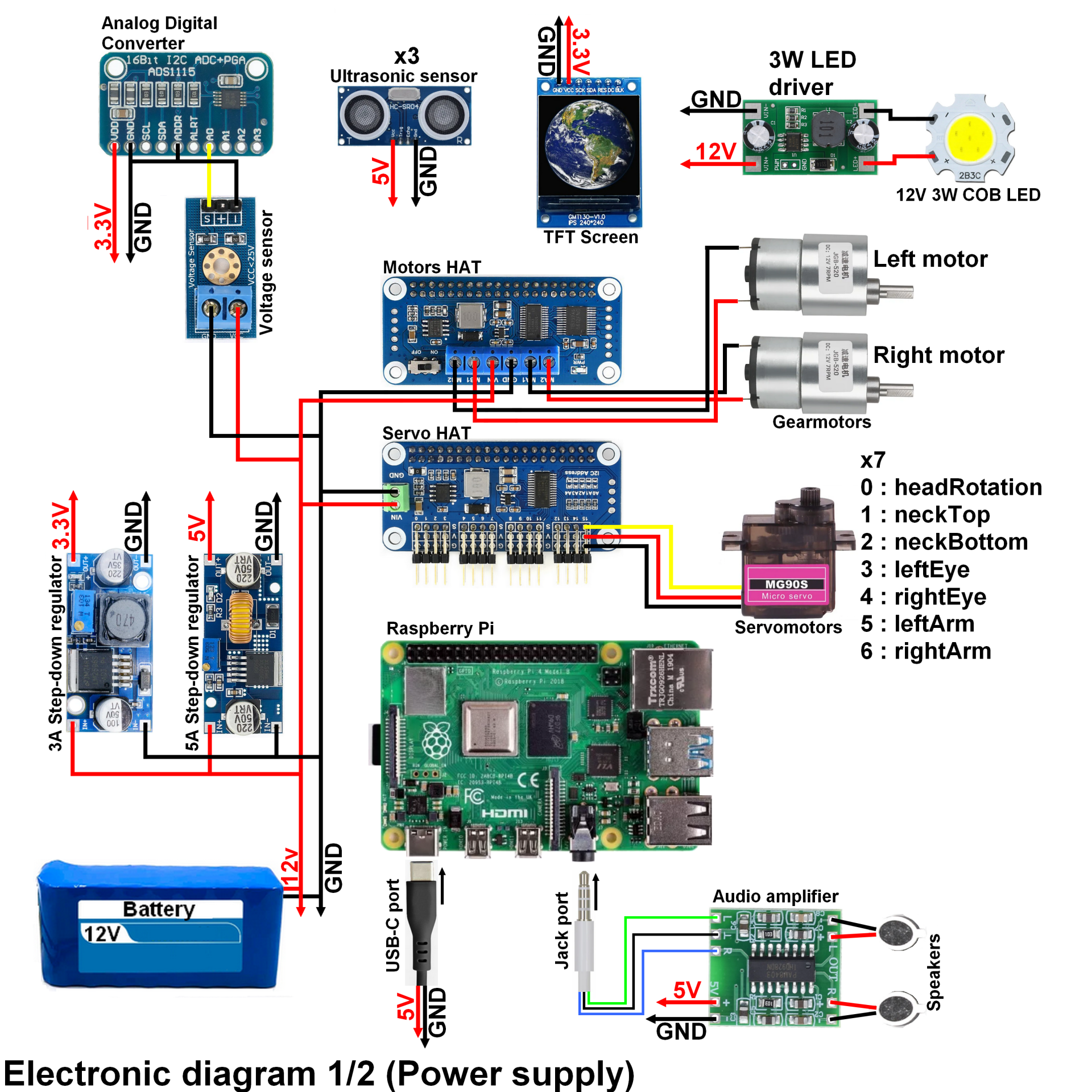
My WALL-E robot is able to move on flat ground, it can raise/lower its arms as well as move its head from left to right and up and down. He is also able to express himself through pre-recorded audios and he has a small screen to show his battery level. Finally, a camera already present will allow him in the future to move independently with the help of 2 ultrasonic sensors as well as a powerful LED which will light up when the ambient light is too low. To control all this, WALL-E has a web interface that can be accessed to interact with it manually.

(FR)

WALL-E est un mignon petit robot présent dans le film Disney du même nom. J'ai eu pour envie de le reproduire pour pouvoir mettre en oeuvre mes compétences afin de les améliorer et surtout pour pouvoir découvrir l'utilisation de l'IA.

Mon robot WALL-E est capable de se déplacer sur un terrain plat, il peut lever/baisser ses bras ainsi que bouger sa tête de gauche à droite et de haut en bas. Il est également capable de s'exprimer grâce à des audios pré-enregistrés et il possède un petit écran afin de montrer son niveau de batterie. Pour finir, une caméra déjà présente lui permettra dans le futur de se déplacer en autonomie avec l'aide de 2 capteurs à ultrasons ainsi qu'une puissante LED qui s'allumera lorsque la luminosité ambiante est trop basse. Pour contrôller tout ça, WALL-E possède une interface web à laquelle on peut accéder afin d'intéragir avec lui de façon manuelle.

Nomenclature / Nomenclature

(EN)

The total price is around 200€

(FR)

Le prix total est d'environ 200€

3D printing / Impression 3D

(EN)

For this project, I looked for an already existing 3D model of WALL-E which was created in order to motorize it. The chillibasket model available on Thingiverse is perfect for this. In addition, many people have already created remixes to improve the basic model. I also made some modifications myself on the model in order to adapt certain parts. Finally, I collected all the 3D models that I used in a collection.

Link to Thingiverse (Collection) (Thanks a lot to chillibasket for his work!)

(FR)

Pour ce projet, j'ai cherché un modèle 3D déjà existant de WALL-E qui ai été créé afin de le motoriser. Le modèle de chillibasket disponible sur Thingiverse est parfait pour cela. De plus de nombreuses personnes ont déjà créé des remix afin d'améliorer le modèle de base. J'ai également moi-même fait quelques modifications sur le modèle dans le but d'adapter certaines pièces. Enfin, j'ai rassemblé tous les modèles 3D que j'ai utilisé dans une collection.

Lien vers Thingiverse (Collection) (Merci beaucoup à chillibasket pour son traval !)

Electronic diagram / Schéma électronique

(EN)

Electronic diagram 1/2 : This first electronic diagram mainly corresponds to the power supply of the various WALL-E component elements.

  • The 5A step-down module should be set to 5V with the potentiometer screw. As for the 3A one, it must be set to 3.3V. I put some hot glue on the potentiometers to make sure they won't go wrong over time.
  • The raspberry does not have an analog-to-digital converter (ADC), which is why I use an ADS1115 (4 inputs) with a voltage sensor. The output signal of the latter must be sent to one of the 4 ADC inputs.
  • The 7 servomotors are connected one after the other from channel 0 to channel 7 as shown in the diagram.
  • When connecting the motors, it may be necessary to reverse the connections so that they work in the correct direction.

(FR)

Electronic diagram 1/2 : Ce premier schéma électronique correspond principalement à l'alimentation des différents éléments composants WALL-E.

  • Le module abaisseur de tension 5A doit être réglé sur 5V grâce à la vis du potentiomètre. Quant à celui de 3A, il doit être réglé sur 3.3V. J'ai mis un peu de colle chaude sur les potentiomètres afin de m'assurer qu'ils ne se dérègleront pas avec le temps.
  • Le raspberry ne possède pas de convertisseur analogique numérique (CAN), c'est pourquoi j'utilise un ADS1115 (4 entrées) avec un capteur de tensions. Le signal en sortie de ce dernier doit être envoyé à l'une des 4 entrées de CAN.
  • Les 7 servomoteurs sont branchés à la suite les uns des autres du canal 0 au canal 7 comme indiqué sur le schéma.
  • Pour le branchement des moteurs, il sera peut être nécessaire d'inverser les branchements afin qu'ils fonctionnent dans le bon sens.

(EN)

Electronic diagram 2/2 : This second electronic diagram corresponds to the connection of the various modules on the Raspberry Pi.

  • The ST7789 display I'm proposing in the BOM doesn't have a CS (Chip Select) pin, which is problematic when using it. To solve this problem, I cut the BLK (Backlight) route, so the BLK pin is no longer connected. It will then serve as the CS pin. And the other end of the cut route will be constantly powered by VCC. For this, I used this guide.
  • Pay attention to the connection of the ultrasonic sensors. You have to supply them with 5V, and the Raspberry Pi sends them a 3.3V pulse on the Trig pin. But the Echo pin of the sensors will send a 5V pulse back to the Raspberry, which will destroy the Raspberry inputs! To avoid this, you must add a voltage divider bridge, which is why two resistors of 1kΩ and 2kΩ are present in the diagram. The GND pin of the sensors is connected directly to the GND of the associated power supply.
  • There is also the LED on the front of WALL-E which must be supplied with 2.2V. A 56Ω resistor is therefore placed in series with the LED in order to limit the voltage.
  • The HAT boards and the Raspberry Pi are nested together, with the motor HAT board above to facilitate assembly/disassembly (this direction is not mandatory).

(FR)

Electronic diagram 2/2 : Ce second schéma électronique correspond au branchement des différents modules sur le Raspberry Pi.

  • L'écran ST7789 que je propose dans la nomenclature ne possède pas de broche CS (Chip Select), ce qui pose problème dans son utilisation. Pour résoudre ce problème, j'ai coupé la route du BLK (Backlight), ainsi la broche BLK n'est plus reliée. Elle va alors servir de broche pour le CS. Et l'autre bout de la route coupée va être constamment alimentée par le VCC. Pour cela, j'ai utilisé ce guide.
  • Il faut faire attention au branchement des capteurs ultrasons. Il faut les alimenter en 5V, et le Raspberry Pi leur envoie une impulsion en 3.3V sur la broche Trig. Mais la broche Echo des capteurs va renvoyer une impulsion 5V au Raspberry, ce qui va détruire les entrées du Raspberry ! Pour éviter cela il faut ajouter un pont diviseur de tension, c'est pourquoi deux résistances de 1kΩ et 2kΩ sont présents dans le schéma. La broche GND des capteurs est branché directement au GND de l'alimentation associée.
  • Il y a également la LED de la face avant de WALL-E qui doit être alimenté en 2.2V. Une résistance de 56Ω est donc mise en série avec la LED afin de limiter la tension.
  • Les cartes HAT et le Raspberry Pi sont emboitées les uns aux autres, avec la carte HAT des moteurs au dessus afin de faciliter le montage/démontage (ce sens n'est pas obligatoire).

Summary table of connections to the Raspberry Pi
      Raspberry pin             TFT screen              Raspberry pin LED driver
BCM 13 / GPIO 27 BLK BCM 7 / GPIO 4 SIG
BCM 18 / GPIO 24 DC BCM 9 / GND GND
BCM 22 / GPIO 25 RES
BCM 19 / GPIO 10 SDA LED
BCM 23 / GPIO 11 SCK BCM 29 / GPIO 5 VCC
BCM 30 / GND GND
ADC module
BCM 3 / GPIO 2 SDA Ultrasonic sensor (right)
BCM 5 / GPIO 3 SCL BCM 11 / GPIO 17 TRIG
BCM 12 / GPIO 18 ECHO
Ultrasonis sensor (left)
BCM 11 / GPIO 17 TRIG Ultrasonic sensor (front)
BCM 12 / GPIO 18 ECHO BCM 31 / GPIO 6 TRIG
      BCM 32 / GPIO 12 ECHO


(EN)

Electronic diagram (optional) : It is possible to make several modifications in order to simplify the electronics and the use of WALL-E.

  • I added a power connector in order to be able to connect the robot with a mains power supply.
  • I made a card with several terminals. I put a terminal block there for each of the two power connectors, one for a switch and one for each of the 6 modules which is supplied with 12V. I soldered a double Schottky diode (MBR1560CT) so that one of the power supplies cannot go up into the other power supply and thus burn one of them.
     
  • I added Dupont connectors between the power supplies (5V and 3.3V) and the various modules in order to facilitate the assembly/disassembly of the electronics.

(FR)

Electronic diagram (optional) : Il est possible d'apporter plusieurs modifications dans le but de simplifier l'électronique et l'utilisation de WALL-E.

  • J'ai ajouter un connecteur d'alimentation afin de pouvoir brancher le robot grâce à une alimentation secteur.
  • J'ai fabriquer une carte avec plusieurs borniers. J'y ai mis un bornier pour chacun des deux connecteurs d'alimentation, un pour un interrupteur et un pour chacun des 6 modules qui est alimenté en 12V. J'ai soudé une double diode Schottky (MBR1560CT) pour que l'une des alimentations ne puisse pas remonter dans l'autre alimentation est ainsi faire bruler l'une d'elle.
     
  • J'ai ajouté des connecteurs Dupont entre les alimentations (5V et 3.3V) et les différents modules afin de faciliter le montage/démontage de l'électronique.

Programming / Programmation

(EN)

WALL-E runs on ROS2. ROS2 is an open-source middleware (software overlay) that provides tools and libraries for prototyping and operating a robot. It allows the various elements (sensors, processing, actuators, etc.) that make up the robot to communicate with each other. To learn more, I recommend you visit the ROS2 website directly.

Link to the project's Github

(FR)

WALL-E fonctionne grâce à ROS2. ROS2 est un middleware (surcouche logicielle) opensource qui qi fournit des outils, des librairies pour prototyper et faire fonctionner un robot. il permet ainsi de faire communiquer entre eux les différents éléments (capteurs, traitement, actionneurs, etc) qui compose le robot en question. Pour en apprendre davantage, je vous conseille d'aller voir directement sur le site de ROS2.

Lien vers le Github du projet

Final render / Rendu final

Future improvements / Futures améliorations

(EN)

  • One of the first improvements to be made is to change the servo motor that moves the robot's neck up/down and replace it with an MG996 servo motor. The originally planned MG90S is far too weak to be able to lift the neck and head properly.
  • A big improvement, and not the least, would be to replace the Raspberry Pi 4 with a more powerful microcomputer. It is possible to replace it with a Raspberry Pi 5 or an Nvidia Jetson Nano. The additional CPU/GPU power will allow the calculations made by the AI to be carried out more quickly. However, there is another solution. It is possible to transfer the calculations made by the AI to a PC which is connected to the robot. However, I personally would not take this solution, because I don't want to have a PC constantly on to be able to run WALL-E.
  • I also plan to add a 3rd and final ultrasound sensor on the front of the robot. This will allow him to be able to manage the obstacles present in front of him.
  • Develop and add the automatic mode that was planned. The robot will be able to move independently (detection of walls / obstacles). He will be able to follow a person and say hello to a waving person.

(FR)

  • L'une des premières améliorations à faire est de changer le servomoteur faisant monter/descendre le cou du robot et de le remplacer par un servomoteur MG996. Le MG90S prévu à l'origine est beaucoup trop faible pour pouvoir soulever le cou et la tête correctement.
  • Une grosse amélioration et pas des moindres, serait de changer le Raspberry Pi 4 par un micro-ordinateur plus puissant. Il est possible de le remplacer par un Raspberry Pi 5 ou par une Nvidia Jetson Nano. La puissance CPU/GPU supplémentaire permettra de réaliser les calculs fait par l'IA plus rapidement. Malgré tout, il existe une autre solution. Il est possible de déporter les calculs fait par l'IA sur un PC qui est connecté au robot. Cependant, je prendrai personnellement pas cette solution, car je n'ai pas envie de devoir avoir un PC constamment allumé pour pouvoir faire fonctionner WALL-E.
  • J'ai également prévu d'ajouter un 3ème et dernier capteur ultrason sur le devant du robot. Cela lui permettra de pouvoir gérer les obstacles présents devant lui.
  • Développer et ajouter le mode automatique qui a été prévu. Le robot sera capable de se déplacer en autonomie (détection des murs/obstacles). Il sera capable de suivre une personne et de dire bonjour à une personne qui fait coucou de la main.

Pictures / Images

Last edited: Sat 29 march 2025

Add a comment

Select the image visible the fewest times

Managing cookies

thedraill.e-monsite.com deposits cookies to improve your browsing experience, measure the website audience, display personalized advertisements, carry out targeted campaigns and personalize the site interface.